Anonymous
Overlay networks are virtual networks formed by cooperating nodes that share an underlying physical network. They represent a flexible and deployable approach for applications to obtain new network semantics without modification of the underlying network, but they suffer from efficiency concerns. Two router-based primitives help end-hosts alleviate these inefficiencies. Packet Reflection allows end-hosts to request that routers perform routing and duplication for certain packets. Path Painting facilitates building overlay topologies that resemble the topology of the underlying network. We describe detailed implementation rules for the proposed primitives, and examine the necessary overhead (in time and space) for their implementation, including hardware implementations.
Simulations with an implementation of application-level multicast and other overlay applications indicate that when all routers support the primitives, less than 5% overhead (in terms of link usage and latency) remains from the purely end-host implementations. In addition, the benefits gained from deployment are significant even at low levels. When intelligent deployment strategies are used, link usage overhead is less than 30% with less than 10% deployment. Finally, these benefits apply mostly to the area local to the deployed routers, providing a deployment incentive to independent networks.
Overlay networks are a popular method for deploying distributed services without having to modify the IP protocols. Example services that have been implemented as overlay networks include multi-path and indirect-routing for high reliability [20,1], teleconference applications [12], and reliable single-source multicast [13,9,6]. These overlay networks perform packet routing and duplication in edge nodes, using only IP unicast between the overlay nodes. In these systems, cooperating servers throughout the Internet act as routers in an overlay network.
Just as a physical network has a topology consisting of the nodes of the network and the links between them, an overlay network has a virtual topology, which exists by the agreement of the overlay nodes. Overlays transmit packets only along the virtual links between the overlay nodes using the underlying unicast mechanism provided by IP.
The overlay network approach faces two important challenges. First, overlay networks operate at a disadvantage to router-based systems because they are located at the edges of the network. This drawback is both a performance problem, packets going in and out of external servers waste time and bandwidth; as well as a functional problem, overlay nodes are not in a position to observe network traffic that is not explicitly directed to them. For example, the IP Multicast (IPM) group joins rely on the ability of routers to observe passing messages.
Second, it can be difficult to build virtual topologies that resemble the topology of the underlying network. It is beneficial for the virtual links of an overlay network to connect nodes that are well-connected in the underlying network. Choosing well-connected virtual links is akin to supplying a physical network with a higher bandwidth link-layer. It is also common to prefer virtual links that share as few underlying links as possible with other virtual links. This property leads to independent failures, and less duplicate traffic on underlying links. Unfortunately, it is difficult to determine these characteristics today, due to complications such as temporary network congestion, route flaps, firewalls, and route asymmetry. Overlays have relied on wasteful and error-prone techniques such as continual bandwidth probes to learn about the underlying network.
We will use two metrics to evaluate how efficiently an overlay network is operating. Stress indicates the number of times that a semantically identical packet traverses a given link. In IPM, stress is exactly one -- a packet is never emitted twice on the same link. On the other hand, traditional overlay networks can not hope to achieve such efficiencies. Packets being forwarded by an edge node will traverse (at least) the node's local link twice. Stretch indicates the ratio of latency in an overlay network compared to some baseline, generally IP unicast or multicast.
The contributions of this paper are:
In contrast to related work (see Section 7), packet reflection and painting are incrementally deployable and don't affect correctness (applications will perform correctly in the face of routing changes). The primitives are for optimization only. Overlay networks must be prepared to operate as if the primitives do not exist. When the primitives are available, the network will provide explicit signaling to the application, allowing it to avoid work that has been performed in the network.
In an overlay network each node carries out explicit unicast communication with its neighbors in the topology. When one overlay node forwards packets between two other nodes, that packet is transmitted on the same link multiple times as it reaches the intermediate and is retransmitted toward the final destination. The links near the intermediate will have a stress of two, and the stretch of the packet will exceed one as time is wasted while the packet approaches and then leaves the overlay router.
When multicasting on an overlay network, the stress problem is exacerbated.
The forwarding node duplicates packets, forcing semantically equivalent
packets to be transmitted on the same link, in the same direction, multiple
times. In such cases, some links will have a stress equal to the number of
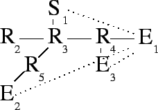
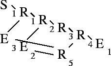
packet duplications plus one. For example, Figure 1
shows a simple application-level multicasting tree in which one link, ![]() , has a stress of three, while another link,
, has a stress of three, while another link, ![]() , has a stress of
two.
, has a stress of
two.
Stretch is also a problem in Figure 1. ![]() receives
packets only after they have traversed seven links, rather than the three
of a direct unicast.
receives
packets only after they have traversed seven links, rather than the three
of a direct unicast. ![]() must wait for five traversals instead of three.
Assuming unit latencies, these paths represent a stretch of 2.3 and 1.7
respectively.
must wait for five traversals instead of three.
Assuming unit latencies, these paths represent a stretch of 2.3 and 1.7
respectively.
 |
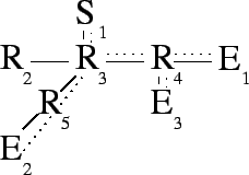
Packet reflection allows an end host to ask an appropriate router to
perform routing and duplication on its behalf. In
Figure 2, end host ![]() directs a reflection request
toward
directs a reflection request
toward ![]() , which takes it to router
, which takes it to router ![]() . This optimization alleviates
stress on link
. This optimization alleviates
stress on link ![]() . In addition to performing requested reflections,
routers continue to forward packets using their normal forwarding
rules. Thus,
. In addition to performing requested reflections,
routers continue to forward packets using their normal forwarding
rules. Thus, ![]() will continue to receive all packets addressed to it.
will continue to receive all packets addressed to it.
 |
The format of a reflection request is
![]() . Such a request will be addressed to
. Such a request will be addressed to ![]() , and will take advantage
of routing symmetry to direct it to routers that can fulfill the request.
(The real-world effect of asymmetry is discussed at the end of
Section 5.3.) This notation means, ``When a reflectable
packet arrives from
, and will take advantage
of routing symmetry to direct it to routers that can fulfill the request.
(The real-world effect of asymmetry is discussed at the end of
Section 5.3.) This notation means, ``When a reflectable
packet arrives from ![]() , destined for
, destined for ![]() , duplicate it once for each
, duplicate it once for each
![]() . Rewrite the source and destination in each duplicate and
emit each, tagged with the associated
. Rewrite the source and destination in each duplicate and
emit each, tagged with the associated ![]() . Emit the original packet
tagged with
. Emit the original packet
tagged with ![]() .'' Tags are used to ensure that nodes know when their
reflection requests have been honored (we will see that network asymmetry
and route changes can cause packets to ``miss'' the router that would
reflect them). Tags are described in detail in Section 2.2. The
operation of a router receiving a reflection request and handling packets
that match the request are formalized in
Rules 1 and 2. In all rules,
``address'' refers to an IP address and a demultiplexing field, similar to
a TCP or UDP port.
.'' Tags are used to ensure that nodes know when their
reflection requests have been honored (we will see that network asymmetry
and route changes can cause packets to ``miss'' the router that would
reflect them). Tags are described in detail in Section 2.2. The
operation of a router receiving a reflection request and handling packets
that match the request are formalized in
Rules 1 and 2. In all rules,
``address'' refers to an IP address and a demultiplexing field, similar to
a TCP or UDP port.
 |
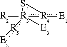
When end hosts initiate reflection requests, they decrease stress on the
link between themselves and the nearest router to them. When routers
themselves make reflection requests, stress is alleviated within the
network. In Figure 3, router ![]() takes advantage of
packet reflection by propagating part of its responsibility to reflect
packets. By pushing a request similar to
takes advantage of
packet reflection by propagating part of its responsibility to reflect
packets. By pushing a request similar to ![]() 's original request on to
's original request on to
![]() ,
, ![]() reduces the stress on link
reduces the stress on link ![]() .
.
If ![]() performs the reflection to
performs the reflection to ![]() ,
, ![]() should not. Tags allow
should not. Tags allow
![]() to know whether a given packet has already been reflected by
to know whether a given packet has already been reflected by ![]() .
This mechanism is formalized in Rule 3 and described in
more detail in Section 2.2.
.
This mechanism is formalized in Rule 3 and described in
more detail in Section 2.2.
An OFFER contains a subset of the copies requested in the ASK, and a nonce. The subset of copies are those copies that the router is willing to make on the requester's behalf. An OFFER is addressed to the destination of the match request, which is not necessarily the originator of the ASK. The asker must intercept the OFFER on its way to its destination. This is a security precaution that ensures that only routers that could intercept traffic destined for a host can request that packets for the host be duplicated and emitted to a third party. Thus no greater power to eavesdrop has been created. The nonce is the result of a one-way hash function run on the match criteria of the request and a router secret thereby ensuring that a router can not respond to an OFFER that it has not actually seen.
The router may determine the subset of copies that it is willing to perform in any way it chooses, though Rule 4 is a guideline. Generally, a router should be willing to make a copy if, when consulting its own IP routing table, it determines that the copy would not be emitted on the same interface as a packet that meets the matching criteria of the ASK. Rule 4 means that a router would make a copy if doing so would decrease stress on one of its own links.
Alternatively, Rule 5 is a recursive approach to determining what copies a router should offer. In this formulation, ASK packets would recursively propagate to the source, then a series of OFFER packets would propagate back to the original asker. Finally, DEMAND packets would proceed toward the sender. The recursive approach will push requests further into the network at the cost of more network traffic during setup.
A DEMAND is the final phase of a reflection request, and is made by the same node that sent the ASK. A DEMAND is sent in response to an OFFER, and contains the nonce of the OFFER. It will also usually contain the same copy information as the OFFER. However, the demander may choose to eliminate some copy requests and, in some cases, must do so in order to maintain the correctness of success tags. A rule for constructing DEMAND packets is deferred until tags are described.
In the presence of route assymetry, a router may accept a reflection request but is not in a position to observe the packets that match the reflection criteria. Similarly, when routes in the underlying network change a reflection request may have propagated to a router that no longer sees the packets that are to be reflected. The requester must know, when it observes the packets, that they have not yet been duplicated.
To address these problems, packet reflection requests contain a tag, as do all packets forwarded by the reflection mechanism. When a router performs a reflection, it writes the value of the tag for that reflection request to the original packet, which is forwarded toward the original destination. If a packet is received without the appropriate tag, it is clear that duplication did not occur, so the receiver performs the duplication.
When choosing a success tag, a router must ensure that the meaning of the tag is unambiguous. However, using the same success tag in successive requests mitigates the deleterious effects of route asymmetry and route changes. End-hosts use a success tag of 1 when initiating a request, and increment the tag when necessary to avoid ambiguity.
In Figure 3, ![]() has requested that two copies be
made whenever it receives a packet from
has requested that two copies be
made whenever it receives a packet from ![]() .
. ![]() agreed to perform
those copies, but went on to request that
agreed to perform
those copies, but went on to request that ![]() should make one of the
copies. The second request incremented the success tag in case the
should make one of the
copies. The second request incremented the success tag in case the ![]() packet emitted by
packet emitted by ![]() ever makes it to
ever makes it to ![]() without passing through
without passing through
![]() .
. ![]() is ensuring that
is ensuring that ![]() will not confuse
will not confuse ![]() with a claim
that is not true. A success tag of 1 would indicate that both copies have
been sent, so
with a claim
that is not true. A success tag of 1 would indicate that both copies have
been sent, so ![]() must use a different success tag after making only one
copy.
must use a different success tag after making only one
copy.
 |
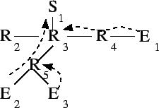
Changing success tags is not always necessary. In
Figure 4 ![]() was able to request that
was able to request that ![]() perform
both copies on its behalf, so the tag was not changed. If the
perform
both copies on its behalf, so the tag was not changed. If the ![]() packet emitted by
packet emitted by ![]() ever makes it to
ever makes it to ![]() without passing through
without passing through
![]() ,
, ![]() will not be confused. The success tag is accurate -- both
copies requested by
will not be confused. The success tag is accurate -- both
copies requested by ![]() have been made. This arrangement also simplifies
have been made. This arrangement also simplifies
![]() 's responsibilities.
's responsibilities. ![]() has arranged matters so that its operation
under Rule 8 has led to a degenerate case: the
incoming packet's tag is the same as the expected tag, and no copy entries
are NORMAL,
has arranged matters so that its operation
under Rule 8 has led to a degenerate case: the
incoming packet's tag is the same as the expected tag, and no copy entries
are NORMAL, ![]() may simply forward the original packet.
may simply forward the original packet.
There is a significant advantage to avoiding unnecessary tag changes. If a
new link were brought up connecting ![]() directly to
directly to ![]() , reflection
would proceed without difficulty. The packet would be tagged at
, reflection
would proceed without difficulty. The packet would be tagged at ![]() in
exactly the way that
in
exactly the way that ![]() expects, so
expects, so ![]() would correctly detect that
its request has been fulfilled. The fact that
would correctly detect that
its request has been fulfilled. The fact that ![]() , rather than
, rather than ![]() ,
performed the duplications is irrelevant.
,
performed the duplications is irrelevant.
In fact, ![]() may safely throw out the reflection table entry associated
with the request as described in Rule 7. Routers
should not eliminate this state without cause, however. If a new route
should be added to the network that skips
may safely throw out the reflection table entry associated
with the request as described in Rule 7. Routers
should not eliminate this state without cause, however. If a new route
should be added to the network that skips ![]() but not
but not ![]() , it would be
beneficial for
, it would be
beneficial for ![]() to maintain enough information to perform the
necessary duplications. If the state has been eliminated, the packet will
not be duplicated until it reaches
to maintain enough information to perform the
necessary duplications. If the state has been eliminated, the packet will
not be duplicated until it reaches ![]() .
.
Once a router has agreed to service a reflection request, it is expected to make the appropriate copies or ensure that another router has done so. Rule 8 refines Rule 2 to describe a router's forwarding responsibilities in the presence of tags.
In addition to the tag associated with the request as a whole, reflection requests also contain a tag associated with each copy. These tags are necessitated by the interaction of multiple reflection requests. Suppose that a router has accepted a request that causes it to emit a packet which would match another of its table entries. Upon receiving the original packet, two table entries would be triggered, and two success tags would be written - one to the original packet and one to the packet that triggered the second entry. Suppose further that the router wants to move this responsibility further into the network. It must be possible to ask that the next router not only perform the duplication, but also write the appropriate tag in the duplicated packet. Rule 9 codifies the way in which these two table entries may be collapsed, bringing the success tag of the second entry into the copy entry of the first match.
Rule 9 places non-zero tags in the copy entries of a reflection table entry. Those non-zero tags indicate that additional copies are being made. Therefore, if they are passed on in a reflection request, the associated copies must be reflected as well. This is described in Rule 10.
To build overlays that resemble the underlying network, nearby nodes should aggregate into small clusters, which then aggregate into larger clusters, and so on. Path painting allows this aggregation by taking advantage of the fact that, in general, the Internet is organized so that nearby nodes share most of their paths to far away nodes. Locally, the nodes of a single university dorm share almost all of their paths. All computers of the university also share most of their paths, though not necessarily the first few hops. Beyond that, all customers of the university's ISP share paths once they reach the ISP, and so on.
To use path painting, end-hosts send paint requests toward an agreed upon rendezvous. As the requests move toward the rendezvous, they meet at routers, and notifications are sent, informing end-hosts of these ``collisions''. Figure 5 shows the interactions of three paint requests. The first painter emits a paint request which paints all routers on the way to its destination. After that, two more painters emit paint requests that proceed only until they reach a router that has already been painted.
 |
The NOTIFY packet, sent in response to the REQUEST, contains the addresses of nodes that have sent REQUEST packets to the same destination. A NOTIFY packet will contain address information about exactly one or two nodes. The first address will always be the current color of the router sending the NOTIFY. When responding to a REQUEST from the node that is currently coloring the node, that will be the only address in the response. When responding to another node, that node's address will be the second address. A separate copy of the NOTIFY is sent to each of the painters in the response. Rule 11 summarizes.
To avoid a denial of service attack from a node that might paint to a path
but refuse to participate with other nodes painting to the same
destination, a request may contain any number of ignore addresses. A
paint request will continue even if it encounters a router colored by one
of the ignore nodes. Suppose that ![]() , the first to paint the path
to
, the first to paint the path
to ![]() , was a malicious node. Without ignore,
, was a malicious node. Without ignore, ![]() and
and ![]() would have been unable to rendezvous. Their paint requests would be
dropped, leaving them without knowledge of any cooperative nodes.
would have been unable to rendezvous. Their paint requests would be
dropped, leaving them without knowledge of any cooperative nodes. ![]() and
and ![]() are expected ignore
are expected ignore ![]() when they detect the difficulty
(perhaps
when they detect the difficulty
(perhaps ![]() is unable to participate in an application-level
authentication mechanism).
is unable to participate in an application-level
authentication mechanism).
This section address some common details of implementation among the two primitives. Both primitives rely on a soft state mechanism to manage storage, and both can be deployed incrementally.
As for reflection, paint state is maintained as soft state and end hosts must repeat their paint requests periodically. All paint requests return NOTIFY packets as they encounter enabled routers. These notifications act as acknowledgments so that paint requests may be retransmitted in case of loss. This reliability allows end hosts to know when a router's state was last refreshed, so that the time of the next refresh can be determined.
This paper does not explore appropriate timeout intervals for refreshing soft state, though it is expected that timeouts on the scale of minutes would be appropriate.
Further encouraging deployment, a router is likely to experience less total load compared to a purely end-host based multicast system. If overlay networks become more common, network operators will want to support reflection for their own benefit (cheaper provisioning), not just for their customers'. Instead of receiving multiple packets, performing multiple route lookups, and transmitting multiple packets, a reflecting router receives one packet, performs one lookup, and transmits multiple copies of the packet. Additionally, the lookups performed for packet reflection may be faster than a normal routing lookup, as they are exact matches rather than longest-prefix matches.
Packet reflection and paint requests are normal IP datagrams, so requests pass through legacy routers unchanged. If, for example, only the border router of a large organization's network is capable of packet reflection, then all reflection requests for flows originating outside of the organization would make their way to the border router. The effect is that all such flows are short-circuited at the border router, saving the organization from internal resource usage. Similarly, as long as at least one router on the shared portion of two nodes' paths to the rendezvous is ``paint capable'', information will be gained that will allow the overlay topology to more accurately reflect the underlying topology.
The primitives presented are intended to be flexible, supporting overlay networks of all kinds. In some cases, such usage is obvious. For example, i3 or a RON could use refection when forwarding packets between two hosts through a third party. Section 6.3.2 describes experiments of this type and evaluates their success.
This section presents various uses of the primitives in multicasting applications. First, an application-level multicast protocol with semantics similar to IP Multicast is presented. Next we will show that, when using the primitives, it is easy to extend a simple IPM-like system to handle heterogeneity and reliability. This flexibility is in stark contrast to IP Multicast, in which support for heterogeneity and reliability represent significant design efforts.
We begin by describing a mapping between features of IP Multicast to elements of the emulation that can be provided with the proposed primitives.
| Feature | IP Multicast | Emulation |
| Group address | Class E IP address | (IP address, port) |
| Rendezvous | Core router | End host |
| Join request | Graft message | Paint request |
| Data Path | Routing table | Reflection state |
As in IP Multicast, a join message is sent to the rendezvous point by new group members. In emulation, the join message is a paint request. If the paint request encounters no router that is already painted on its way to the rendezvous, then no action is required; the new node is the only member of the group. If the paint request encounters an already painted router, that router notifies the joining node and the previous painter.
One of these two nodes must become the parent of the other. Various rules are possible, but one rule that appears promising is to set the node nearer to the router at which the collision occurred to be the parent. The nodes can determine their nearness from the TTL field in the collision reports. In case of a tie, any tie breaker is sufficient, such as an ordering on the nodes' IP addresses. More simply, they can rely on the router to select a paint color, which will be the first painter.
Once the nodes have decided who will be the parent, the child begins sending paint request with concede set to the address of the parent. On the other hand, if the other node is uncooperative, the emulation adds the node to the paint request's ignore list.
In Figure 6, three nodes have joined an emulated
multicast group using ![]() as a rendezvous. The end-hosts sent paint
requests in their natural order (
as a rendezvous. The end-hosts sent paint
requests in their natural order (![]() ,
, ![]() , then
, then ![]() ), and the
topology induced by that ordering was acceptable.
), and the
topology induced by that ordering was acceptable. ![]() 's paint reached
's paint reached
![]() , which notified
, which notified ![]() and
and ![]() . These nodes then set up
communication by some application-level protocol.
. These nodes then set up
communication by some application-level protocol. ![]() 's paint then
reached
's paint then
reached ![]() , leading to a similar exchange between
, leading to a similar exchange between ![]() and
and ![]() .
.
The rendezvous, ![]() , is an active participant in the multicast group.
Thus
, is an active participant in the multicast group.
Thus ![]() itself acts as a painting router. When
itself acts as a painting router. When ![]() 's first paint
arrives at
's first paint
arrives at ![]() , a NOTIFY is sent to
, a NOTIFY is sent to ![]() , informing it that it has
reached a router that is colored by
, informing it that it has
reached a router that is colored by ![]() .
. ![]() and
and ![]() carry out the
same protocol to establish communication as
carry out the
same protocol to establish communication as ![]() and its children did.
and its children did.
However, the rendezvous does not need to be an active member of the
multicast group. Suppose ![]() were eliminated, but IP routing entries
still exist for it in its current location.
were eliminated, but IP routing entries
still exist for it in its current location. ![]() 's paint would have
elicited only the ``empty'' NOTIFY packets from
's paint would have
elicited only the ``empty'' NOTIFY packets from ![]() and
and ![]() that
tell
that
tell ![]() that it has colored those routers. When
that it has colored those routers. When ![]() and
and ![]() sent
their paint requests, the group would be formed in exactly the same way as
before. The group would consist only of
sent
their paint requests, the group would be formed in exactly the same way as
before. The group would consist only of ![]() , with its children
, with its children ![]() and
and
![]() .
.
Any member of the multicast group can send packets to the group. To do so,
it sends packets to each of its neighbors. For example, ![]() would need
to send one packet, addressed to
would need
to send one packet, addressed to ![]() .
. ![]() would send three packets,
one to each of its children and to its parent,
would send three packets,
one to each of its children and to its parent, ![]() .
.
First, we observe that only one group member in a stub network will have a neighbor in the distribution tree outside of that stub network. A stub network is a subnetwork that is connected to the portion of the network containing the rendezvous by a single link. A portion of the network that contains the rendezvous is not considered a stub network.
As the paint requests of the members in the stub network travel toward the rendezvous, they all traverse their single connecting link and their border router. Only one group member may color the border router, and only that paint color will be seen outside of the stub network.
Our seconds observation is that stress will never exceed one on the link
connecting a stub network to the rest of the network. The only possible
reasons for a packet to traverse such links are to get to the node,
X, that has colored the border router or from X to one of its
(possibly many) children. Reflection will always eliminate the return
packets by pushing the copies to the external router connected to the
border router. Consider the propagation of the reflection request. The
request must be of the form (tags elided):
As the reflection propagates toward the border router, every router will offer to perform the copies that name destinations outside of the stub network (foreign nodes). A router would only refuse to perform a copy if its destination is in the same direction as X, which is never the case for foreign nodes.
The fact that a stub network's link has a stress of one is surprisingly powerful because our definition of a stub network is quite broad. For example, if the entire network is a tree, then every subtree of the network which excludes the rendezvous is a stub network. Therefore there will be no link with a stress greater than one in such networks. Trees are a common network architecture for networks of small to medium scale implying that multicast trees built in this way will be very efficient in many real world scenarios.
However, a portion of the network that is not a tree can have stress
greater than one. This occurs when a reflection request does not propagate
to the router at which the associated paint collision occurred.
Figure 7 illustrates such a situation. Assume that
routing is by shortest path and that each link has unit weight. After
being the first to paint to ![]() ,
, ![]() finds itself the parent of
finds itself the parent of ![]() and
and ![]() . It formulates the following reflection request (tags elided):
. It formulates the following reflection request (tags elided):
Following Rule 4 ![]() offers to perform both copies.
However, when
offers to perform both copies.
However, when ![]() attempts to pass the request further,
attempts to pass the request further, ![]() will not
offer to perform either copy. This choice is because
will not
offer to perform either copy. This choice is because ![]() would emit the
copies on the
would emit the
copies on the ![]() link, which is the same link on which it will emit
the original (
link, which is the same link on which it will emit
the original (![]() ) packet. The
) packet. The ![]() link retains a stress of
two because it must carry a packet for each of
link retains a stress of
two because it must carry a packet for each of ![]() and
and ![]() .
.
 |
Our assumptions are not necessary for the primitives to perform well. For example, the assumption that the primitives have been implemented at every router is stronger than necessary. Only a router that is located at the collision of two paint requests must implement the primitives. In reality it will be impossible to deploy enabled routers at precisely the locations that they might someday be needed, so we consider how well the emulated multicast system will behave under various deployment scenarios in Section 6.
If the network lacks routing symmetry, some reflection requests will not reach their intended destination. When a reflection request reaches a router that emits packets for the match criteria destination through a different interface than it receives the request, the router's OFFER will not be intercepted by the asker. Reflection will work only on the symmetric portion of the path. We expect that symmetry is common from the edges of the network to border routers and our evaluations demonstrate that even if the primitives are deployed only at border routers, most of their effectiveness is retained. Therefore, we expect real-world asymmetry to have little impact of the effectiveness of reflection.
Unfortunately, too little is known about Internet asymmetry to support useful simulations. The ability of existing topology generators to create detailed topologies that include latency and routing information is limited. Further complicating the picture by adding asymmetric links gives one little reason to believe that the generated topologies would truly resemble Internet topologies with respect to properties like latency and the location of asymmetries. Although we have conducted initial experiments [2], further research detailing the sources and locations of asymmetry in the Internet is needed before any simulation can be trusted.
Using path painting, nodes arrange themselves into an efficient distribution tree as in IP Multicast emulation. Each node makes reflection requests to forward all traffic among its neighbors in the overlay network. Each node also exchanges congestion information with each of its neighbors. If an overlay link is found to be suffering from congestion, then the use of reflection requests to forward along that path is discontinued. Instead, the stream is thinned at each end of the overlay link and forwarded with explicit unicast. The thinning may consist of transcoding to an entirely different lower-fidelity format or by dropping selected packets that are less important to the reconstruction of the data stream.
Stream thinning wherever appropriate creates a system that provides all participants with as much bandwidth as possible to all other participants. When two separate pools of well-connected users are joined by a low-bandwidth connection, the users in each pool will experience high-fidelity contact with the users in their own pool.
The reliable multicast protocol presented here is an extension to the the previous heterogeneous multicast protocol. The distribution tree is set up, and congestion information is exchanged in exactly the same manner. Unlike heterogeneous multicast, the only possible ``thinning'' strategy is to drop packets. All packets must be transmitted in order to transmit a bitwise correct data stream.
Dropped packets must be retransmitted, though the details are up to the application. If links are uncongested it is appropriate for the node that detects the loss to immediately request a retransmission from its parent. When a link is congested and the packet has been dropped explicitly by the parent, the best strategy is to wait until the congestion has subsided before asking for retransmissions.
This section evaluates the effectiveness of the proposed primitives, as measured by decreased stress and stretch, defined in Section 1. The proposed primitives should decrease stress and stretch in all situations, though they can be expected to be most effective when widely deployed.
In addition, the primitives are intended to have modest space requirements in routers. The space required at individual routers should scale slowly, if at all, with the size of the group. Again, we can expect full deployments to meet these goals more easily than sparse deployments.
The simulations presented here use highly-connected transit-stub topologies generated by The Georgia Tech Internetwork Topology Models (GT-ITM) [28]. All simulations were conducted over ten different 100 router graphs. The parameters used to generate these topologies are from the sample graphs in the GT-ITM distribution. Each of the nodes in the GT-ITM graphs models an Internet router. An end host is added at each router to serve as overlay members.
We have implemented reflect and paint as three new Otcl objects for the ns-2 [18] network simulator. ReflectAgent and PaintAgent accept requests from applications. PrimConnector inspects all packets entering a node and implement the rules described in the previous sections. The ns implementation of reflect and painting could be ported easily to software routers or a standard operating system. A hardware implementation would be more challenging and is likely to approach the performance of an IPM router but not meet it [2].
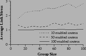
The first experiment examines the scalability of an ALM system in the presence of the proposed primitives. The primitives are expected to allow an ALM system to scale more gracefully. As more routers support the primitives, stress should grow more slowly with group size. Figure 8 demonstrates this claim. Average link stress is plotted against group size for various levels of deployment. The slope of these plots is clearly smaller in experiments in which more routers support reflection and paint, indicating that stress growth is slower when the primitives are more widespread.
 |
Next we compare network stress under four different deployment scenarios. Figure 9 shows the results. It is clear that the enabling of certain routers is far more effective than others. Enabling transit routers, the ``core'' of the simulated network is extremely effective at reducing stress even though they represent only 4% of all routers. They are in an excellent location to be effective as rendezvous points for painting, and then to duplicate packets with reflection.
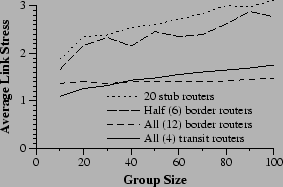 |
Border routers are nearly as effective as transit routers. When all are enabled, they lie on all of the same paths as the transit routers, thus they can eliminate inefficiencies in nearly all of the same cases. They are slightly less effective for small group sizes because of stresses among the transit routers that cannot be relieved without enabled routers in the core. With larger groups, the border routers become more effective. To understand why, consider the ``zone of responsibility'' of a transit or border router. In each case, the router effectively isolates a portion of the network allowing a single packet arriving at the router to be duplicated to service all members in its subtree. From that point on, however, there is, essentially, iterated unicast to those members from the router. Small groups have few members in each ``zone of responsibility'', so stress remains low. Border routers lower stress more effectively for larger groups by splitting the network into smaller subnetworks and avoiding stressing the border-transit link.
The other two scenarios compare deployments that involve some randomness, and do not turn on all routers of the given type. In one, half of all border routers are enabled. In the other, 20 stub routers out of a possible 84, are enabled. Despite the considerably larger number of stub routers, the border router strategy is somewhat more effective (though less consistent as shown by the fact that averaging over 10 topologies was insufficient to smooth the performance of the strategy). In the stub deployment scenario, nothing can be done to ease stress in the core, including the ``expanded core'' consisting of transit routers and border routers. In addition, many stub routers will be completely unused because no group members happen to be located behind them.
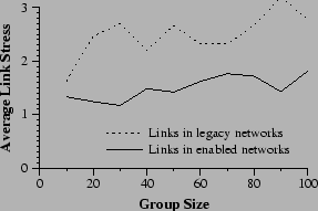
Organizations that deploy painting and reflection will be more interested in the effect on their local portion of the network rather than the network as a whole. One claim of incremental deployment is that local deployment will be of local benefit. To evaluate this claim, we gather more data from one of the previous experiments. In the ``half-border'' scenario, half of the border routers were chosen at random for enabling. We now examine, as separate functions, the stress levels in networks with an enabled border router and networks with a legacy border router. Figure 10 shows that the advantages of deployment are gained in the areas of deployment. Networks with an an enabled border router have stresses in the neighborhood of 1.5. Stress in legacy networks is approximately 2.5, a three-fold increase in overhead.
 |
We examine the effect of the primitives on latency in a repeat of the experiment of Section 6.2. All end-hosts participate in an application-level multicast. A single packet is emitted from the source and arrival times are noted for all group members. For each member, these latencies are compared to the time for IP unicast to transmit from the source directly to the same member. Average stretch is calculated as by computing a stretch for each receiver (latency in ALM divided by latency with unicast) and averaging. The results are graphed in Figure 11.
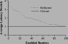 |
Figure 11 shows that, as expected, stretch decreases with increased levels of deployment. At 30% deployment, the primitives have eliminated approximately 60% of the latency overhead. At complete deployment, they have eliminated nearly all added latency.
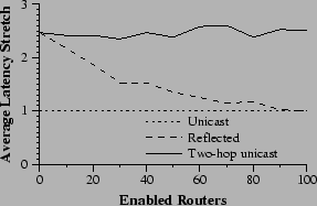
In the following experiment, three nodes are chosen at random to act as the endpoints of communication and the waypoint. Two packet transmissions are timed to set baselines before testing reflection. First, normal IP unicast between the source and destination; then, a two-hop unicast route that uses the waypoint to route packets. These represent the two extremes of possible performance. Finally, after the waypoint sends its reflection request, a third time is measured that represents how well reflection has reduced the two-hop situation to IP unicast.
As usual, the experiment is conducted over the 10 transit-stub topologies at various levels of deployment. In each experiment, 100 triples are randomly selected for measurement. Two stretches are calculated for each triple using the IP unicast time as a baseline. Figure 12 graphs the result.
As deployment increases the performance of the system moves smoothly from that of two-hop unicast case toward that of single unicast. It is encouraging that improvement is fastest at the early stages of deployment. At 30% deployment, the primitives have eliminated well over half of the overhead.
 |
First, we examine the size of the reflection tables in the random deployment experiments of Section 6.2. Randomly selected groups perform ALM in networks with a random selection of enabled routers.
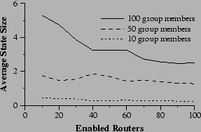 |
Figure 13 shows that the average state requirements decrease as deployment increases. This result is unsurprising. Consider the difference between two networks, one of which has one extra enabled router. In general, that router will receive some amount of state from its downstream neighbors. The amount of state associated with a single reflection request decreases as it is propagated (because some routers see that they cannot fulfill portions of the request). Therefore the new node is likely to receive less state that its downstream neighbors had, bringing the average down. Furthermore, in small groups, it will be common for added routers to find themselves completely unused, lowering the average state requirements.
The maximum state required in any router can be as important as average state requirements. If the state requirements are extremely unbalanced, one router may be forced to carry too much information and refuse requests or experience degraded performance. Although the primitives are designed to degrade gracefully under such circumstances, they will surely perform better if they avoid it.
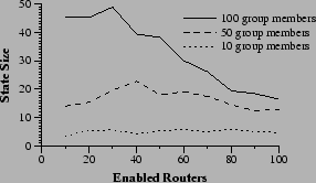 |
Figure 14 examines the maximum state requirement of any router in the same experiments. Two facts are interesting. First, for smaller group sizes, the maximum state held in any one router is nearly constant, regardless of deployment levels. Second, large groups disproportionately load single routers at low deployment levels, but the maximum state held in any one router decreases as deployment increases. This decrease indicates that the work is more smoothly shared when more routers are enabled.
Comparing Figure 14 to Figure 13, we observe that the shapes of the state requirements are similar in each graph. Maximum state size requirements appear to scale with the average state size requirements. This fact indicates that in very large networks, such as the Internet, maximum state requirements should remain manageable if deployment is sufficiently high to keep average state size requirements down.
This paper extends previous work [3] by presenting detailed rules by which routers implement reflection and paint. These rules, as well as additional protocol details address several issues of correctness and security. In addition, the behavior of the multicast system is considered in detail and then analyzed in an extensive performance evaluation that was lacking in the original workshop proposal.
Other related work can broadly be divided into three areas. First, IP Multicast [7] provides a group communication primitive for IP, and a number of systems [8,14,15,17] have attempted to build additional semantics on top of IPM. These efforts have seen limited success, in part because of IPM's limited deployment, and in part because IPM provides a difficult base upon which to build -- IPM is a monolithic primitive combining all needed mechanisms to provide a single high-level abstraction. Single-source extensions to IPM, such as Source-specific Multicast [10] and Express [11] address some of the deficiencies of IPM, such as security and a limited namespace, but remain special purposed.
REUNITE [22] is a multicast protocol that multicasts using recursive unicast distribution trees. As in an overlay network, packets are transmitted from point to point using traditional IP unicast. However, REUNITE uses point to point unicast transmissions between routers, only involving end-hosts at the edges of the tree.
REUNITE accomplishes a number of things that the primitives proposed here also hope to achieve. It is a fairly simple protocol, it is incrementally deployable, and state requirements can be managed explicitly by overloaded routers. REUNITE, however, is aimed strictly at supporting multicast. Path Painting and Packet Reflection support a broader range of applications.
Obviously, existing overlay networks are related, and complementary to the primitives presented here. Some overlays are extremely generic, such as RON [1], X-Bone [23], Dynabone [24], and Yoid [9]. These systems exists solely to provide an overlay network with ``better'' properties than the underlying network, such as lower latency or quicker response to failures. Application-level multicast (ALM) systems, such as RMX [6], End-System Multicast [12], and Overcast [13], are more specific overlay networks. All share the goal of providing the benefits of IPM without direct router support.
Finally, an active networks [27,19] inspired system that provides primitives based on the ability to perform computations on ephemeral state in routers is closely related. An early version of this work [26] describes a primitive, dup, that closely resembles packet reflection, and a number of associated primitives that accomplish goals similar to packet reflection. A strength of dup is that it handles asymmetric routes better than painting and reflection. However, this may come at the cost of scalability - their join mechanism involves an echo packet reaching a central rendezvous point before being returned to the sender. Large groups may overwhelm the rendezvous point's network.
A strength of reflection and painting is that they have been designed to operate correctly in the face of route changes and multi-path routing in the underlying network. Dup is insufficient to handle these cases. For example, if a route change causes the router maintaining a node's dup request to stop receiving the group's packets (because they are now taking a different path), packets will be lost. With reflection, duplications are explicitly confirmed, using success tags. If the duplication point is bypassed, the requester knows it. It can then perform the duplication on its own and make a new reflection request.
A later version of the work [5] concentrates on the ability of emphemeral state computations to gather information, but avoids the complicates of active routing in the network. This work more closely resembles paint, although the ephemeral state approach is more general.
Overlay networks are an important way for applications to obtain network behavior that would otherwise require widespread router modifications. By their very nature, it is possible to deploy overlay networks with no additional support. Yet doing so creates inefficiencies. Path painting and packet reflection address those inefficiencies with simple, incrementally deployable router extensions that can be used in creative ways to perform packet routing and duplication at appropriate locations in the network.
The focus on incremental deployment has created numerous subsidiary benefits. Routers may choose to ignore requests for any reason, ranging from administrative policies, security concerns, or resource exhaustion. All of these cases are handled gracefully because they are functionally identical to routers that do not support the primitives.
Even if only a few routers deploy the primitives, it still results in significant overall benefit. As overlay networks grow in importance, we are hopeful that the proposed primitives will be deployed and reduce the inefficiencies of overlay networks.