Handed out Thursday, November 6, 2008
Due Thursday, November 20, 2008
Use Git to commit your Lab 5 source, fetch the latest version of the course repository, and then create a local branch called lab6 based on our lab6 branch, origin/lab6:
athena% cd ~/6.828/lab
athena% git commit -am 'my solution to lab5'
Created commit 734fab7: my solution to lab5
 4 files changed, 42 insertions(+), 9 deletions(-)
athena% git pull
Already up-to-date.
athena% git checkout -b lab6 origin/lab6
Branch lab6 set up to track remote branch refs/remotes/origin/lab6.
Switched to a new branch "lab6"
athena% git merge lab5
Merge made by recursive.
 fs/fs.c |   42 +++++++++++++++++++
 1 files changed, 42 insertions(+), 0 deletions(-)
athena%
The driver, however, will not be enough to get your OS hooked up to the
Internet. In the new lab6 code, we have provided you with a network stack
and a network server. As in previous labs, use git to grab the code for
this lab, merge in your own code, and explore the contents of the new
net/ and kern/dev/ directories.
In addition to writing the driver, you will need to create a system call interface to give access to your driver. You will implement missing network server code to transfer packets between the network stack and your driver. You will also tie everything together by finishing a web server. With the new web server you will be able to serve files from your file system.
Much of the kernel device driver code you will have to write yourself from scratch. There are no skeleton files and no system call interfaces written in stone. For this reason, we recommend that you read the entire assignment write up before starting any individual exercises.
qemu.sh to make running QEMU easier.
We will be using QEMU's user mode network stack which requires no administrative privileges to run. QEMU's documentation has more about user-net here. The network card can be enabled as follows:
qemu -hda obj/kern/bochs.img -hdb obj/fs/fs.img -parallel /dev/stdout -net user -net nic,model=i82559er
User-net can be viewed like a NAT that sits between JOS and the Internet;
therefore, JOS itself cannot be directly addressed from outside QEMU. QEMU's
NAT runs on the 10.0.2.0 subnet, the default QEMU guest IP address is 10.0.2.15
and the default router IP is 10.0.2.2. The network server needs to use these
defaults and are defined in net/ns.h.
qemu -hda obj/kern/bochs.img -hdb obj/fs/fs.img -parallel /dev/stdout -net user -net nic,model=i82559er -redir tcp:4242::10000Now you can use tools like
telnet or netcat (the command line name
for netcat is nc) to connect to a service running on JOS. For
example, to connect to port 10000 on JOS, run:
telnet localhost 4242
nc localhost 4242
To test your networking code, we have provided a daemon called
tcpsrv. Running tcpsrv will setup an echo server
running on port 10000 that will echo back anything sent over a TCP connection.
If you telnet to the redirected port, anything you type will be
sent back to you.
It is very helpful to examine any packets sent to or received from the host
machine. However, since the details of user-net do not allow easy access to the
packet flow, our version of QEMU provides a mechanism that dumps every packet
that passes through user-net into a file. The file is stored using the pcap
format. This popular packet capture file format allows you to use either
tcpdump or wireshark to examine both the packet flow
and packet structure. Here is how to enable pcap printing in our version of
QEMU:
qemu -hda obj/kern/bochs.img -hdb obj/fs/fs.img -parallel /dev/stdout -net user -net nic,model=i82559er -redir tcp:4242::10000 -pcap slirp.capTo read the captured packets in ASCII use
tcpdump like this:
tcpdump -nnxr slirp.capWireshark is a graphical version of
tcpdump. It is not installed
on Athena, but you are welcome to use it on your own computers.
Note that the -pcap option is only available in our version of QEMU.
qemu -hda obj/kern/bochs.img -hdb obj/fs/fs.img -parallel /dev/stdout -net user -net nic,model=i82559er -redir tcp:4242::10000 -pcap slirp.cap -debug-e100Once the E100 debug command line option is set, the emulated E100 will print debug messages to the terminal where you launched QEMU. It will print lines like this:
EE100   eepro100_write1         addr=Command/Status+1 val=0x20
EE100   disable_interrupt       interrupt disable
Note that the -debug-e100 option is only available in our version of QEMU.
You can take debugging using software emulated hardware on step further. If you are ever stuck and do not understand why the driver is not understanding your commands or it is reporting cryptic message, you can look at the emulated hardware source code for hints. The source for the E100 emulated hardware is in the QEMU tarball.
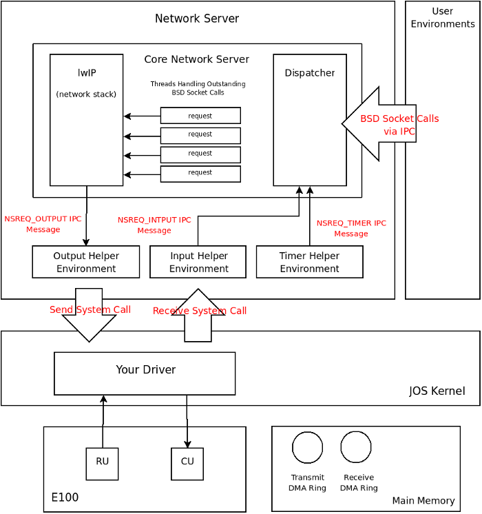
What we call the network server is actually a combination of four environments, they are:
The core network server environment is composed of the socket call dispatcher
and lwIP itself. The socket call dispatcher works exactly like the file server.
User environments use stubs (found in lib/nsipc.c) to send IPC
messages to the core network environment. If you look at
lib/nsipc.c you will see that we use the same trick as in the file
server to name the core network server: we start the network server right after
the file server thereby forcing the ns to have an envid of 2.
For each user environment IPC, the dispatcher calls the appropriate BSD socket
interface function provided by lwIP on behalf of the user. The file server
interface required that we implement a file descriptor to keep track of file
state, lwIP implements this facility for us. The subset of BSD socket calls
that our network server provides can be found in inc/lib.h. Take careful note that
closing a socket descriptor is done by closesocket and not simply
close (this is due to having a separate file and socket descriptor).
Even though it may seem that the IPC dispatchers of the file server and network
server act the same, there is a key difference. BSD socket calls like
accept and recv can block indefinitely. If the
dispatcher were to let lwIP execute one of these blocking calls, the dispatcher
would also block and there could only be one outstanding
network call for the whole kernel. Since this is unacceptable, the network
server uses user level threading to avoid blocking the entire server
environment. For every incoming IPC message, the dispatcher creates a
thread and processes the request in the newly created thread. If the thread
blocks, then only that thread is put to sleep while other threads have a chance
to run.
In addition to the core network environment there are three helper
environments. Not only does the dispatcher accept messages from user
applications, it also accepts messages from the timer environment.
The timer
environment periodically sends messages of type NSREQ_TIMER to the
core network server notifying it that a timer has expired. The timers interrupts
from this thread are used by lwIP to implement TCP timeouts.
Unfortunately, your kernel does not have a notion of time and we need to add
it. We have opted for a simple method of adding time to JOS. There is
currently a clock interrupt that is generated by the hardware every 10ms. On
every clock interrupt we can increment a variable to indicate that time has
advanced by 10ms. This is implemented in kern/time.c, but is not
yet fully integrated into your kernel.
Exercise 1.
Add a call to time_tick for every clock interrupt in
kern/trap.c. Also add a call to sys_time_msec in
syscall in kern/syscall.c so that user space has
access to the time.
NSREQ_OUTPUT IPC message
with the packet attached in the page argument of the IPC message. The output
environment is responsible for accepting
theses messages and forwarding the packet on to the device driver via the
system call interface that you will soon create.
The attached page holds a struct jif_pkt structure (defined in
inc/ns.h).
struct jif_pkt {
    int jp_len;
    char jp_data[0];
};
The first 4 bytes of the page, jp_len, represent the length of the
packet. All subsequent bytes in the page are dedicated to the packet contents.
jp_data in the above structure is a name for the bytes following
jp_len.
NSREQ_INPUT IPC message.
The core network server expects all IPC input messages to have a page
attached with a struct jif_pkt structure filled in.
The packet input functionality is separated from the core network environment
because JOS makes it hard to simultaneous accept IPC messages and poll or wait
for a packet from the device driver. We do not have a select
system call in JOS that would allow environments to monitor multiple input
sources to identify which input is ready to be processed.
If you take a look at net/input.c and net/output.c you
will see that both need to be implemented. This is mainly because the
implementation depends on your system call interface. You will write the code
for the two helper environments after you implement the driver and system call
interface.
Exercise 2. Browse the Intel 82559 page and the 82559 documentation page. In particular look at these two documents:
When you do read the open source developer manual in depth, glance over Section 4 to learn about the PCI interface but pay very close attention to Section 6 as it deals with the Software Interface. In fact, most everything you need is in Section 6. Use the datasheet solely as a reference if you find the developer manual vague.
The acronyms in both documents can get overwhelming. Consult the glossary at the end of this lab assignment for some help.
The E100 is a PCI device, which means it plugs into the PCI bus on the motherboard. The PCI bus has address, data, and interrupt lines, and allows the CPU to communicate with PCI devices and PCI devices to read and write memory. A PCI device needs to be discovered and initialized before it can be used. Discovery is the process of walking the PCI bus looking for attached devices. Initialization is the process of dynamically allocating I/O and memory space as well as negotiating the IRQ line for the device to use.
We have provided you with PCI code in kern/dev/pci.c. A device on
the PCI bus is identified by its functions (a device can have multiple
functions). The E100 happens to have only a single function. Here is how we
represent a PCI function in JOS:
struct pci_func {
    struct pci_bus *bus;

    uint32_t dev;
    uint32_t func;

    uint32_t dev_id;
    uint32_t dev_class;

    uint32_t reg_base[6];
    uint32_t reg_size[6];
    uint8_t irq_line;
};
The above structure corresponds to some of the entries found in Table
1 of Section 4 in the
developer manual. Specifically, the last three entries of
struct pci_func are of interest to us.
The reg_base array holds the negotiated values for the address at which the device
lives, reg_size holds how many addresses have been allocated to each corresponding entry in
reg_base, and irq_line contains the IRQ line
the kernel needs to listen on to receive interrupts from the devices. The 6
entries in the reg_base array correspond to byte offsets 0x10 -
0x24 in Table 1 in the developer manual. Make sure you understand which entries
in reg_base and reg_size are valid and what the valid
entries mean.
During PCI initialization, the PCI code walks the PCI bus looking for devices. As soon as it finds
a device, it read its vendor ID and device ID and uses these two values as a key
to search the pci_attach_vendor array. The array is composed of
struct pci_driver entries like this:
struct pci_driver {
    uint32_t key1, key2;
    int (*attachfn) (struct pci_func *pcif);
};
If there is an entry in the array that matches the vendor ID and device ID, the
corresponding attach function is called to trigger device initialization.
When the attach function of the corresponding device is called, the device is
found but it is not enabled. This means that the PCI code has found a device
but has not yet allocated resources, such as address space and IRQ line, to the
device (the last three elements of the struct pci_func structure
are not valid). The attach function provided by the device driver needs to call
the pci_func_enable function provided by the PCI code to enable the
device and fill in the rest of the struct pci_func.
Exercise 3.
Implement an attach function to initialize the 82559ER. Add an entry to the
pci_attach_vendor array in kern/dev/pci.c to trigger
your function if a matching PCI device is found. The vendor ID and device ID for
the 82559ER can be found in Section 4 of the developer manual.
You should create a data structure private to your driver and record the IRQ line and the base I/O port assigned to the device by the PCI bus. You will need to remember the I/O base port to be able to communicate with the E100.
We have provided the kern/dev/e100.c and
kern/dev/e100.h files for you so that you do not need to mess with
the make system. You may still need to include the e100.h file in
other places in the kernel.
The PCI bus allows a device to be controlled by either memory mapped I/O or dedicated
I/O ports. We advise that you use I/O ports and the inb and
outb family of instructions to communicate with the E100. Using
memory mapped I/O requires thinking about what happens if the compiler or the
CPU reorders memory operations.
The 82559ER is controlled through the Control/Status Registers (CSR). The
CSR is described in Section 6.3 in the developer manual. The CSR is a 64 byte
long data structure that can be accessed by reading or writing ports starting
from the base address given to the device by the PCI bus. The base I/O port
can be found in the struct pci_func PCI structure. You will be working
exclusively with the first 12 bytes of this structure. The System Control Block
(SCB) is the name for the first 8 bytes of the CSR. The SCB is used to control
and get status about the device. The next 4 bytes in the CSR are called PORT
and are used to reset the chip.
Reading and writing to the CSR is simple. For example, to read the low bits of
the SCB status word, you can use inb(base + 0x0). To read the high
bits, you can use inb(base + 0x1). To write a 0xd
into the SCB command word, you can use outw(base + 0x2, 0xd). To
write 0xdeadbeef into the SCB general pointer use
outl(base + 0x4, 0xdeadbeef). The type of command used is very
important. inb is used to read a byte, inw to read 2
bytes and inl to read 4 bytes.
How do you know if you are successfully writing something to the device? That is where the QEMU -debug-e100 command line flag helps. Every time there is a write or read to a register in the CSR, the QEMU emulated E100 will print a message to the console. Look for these messages and make sure they correspond to what you are doing.
There are a couple places where the 82559ER docs specify that a driver must
delay for a certain amount of time before continuing. An example delay function
can be found in kern/console.c. Each inb of port
0x84 takes about 1.25us; four of them, therefore, takes 5us.
Exercise 4. Add code to your attach function to reset the 82559ER. If you set the -debug-e100 flag, QEMU should tell you if the reset was successfully. It will print something like this:
EE100 nic_reset 0xacea498
A DMA ring is a set of buffers allocated in main memory and chained together by pointers. This ring is usually a circular singly-linked list where the pointers are physical addresses of the next buffer in the ring. The pointers need to be physical addresses because a DMA ring is created to be used by a device. A device sitting on the PCI bus (for example) does not have access to the CPU's MMU to translate a virtual address using paging or segmentation into a physical address.
The 82559ER uses DMA rings to allow the driver to specify multiple packet buffers for the 82559ER to use. For example, a receive DMA ring allows the RU access to multiple receive packet buffers. The 82559ER has limited internal memory and can only buffer a few packets in its local memory. During periods of bursty traffic if the CPU cannot service the E100 interrupts promptly, a device without a DMA ring would be forced to drop packets. The 82559ER, on the other hand, can move incoming packets out of its limited local memory and into the DMA ring in the much larger main memory. The 82559ER uses DMA processors to move incoming packets onto the receive DMA ring without waiting for the driver's approval. If the CPU is too busy to handle the E100 interrupts, the received packets will be waiting in the DMA ring when the CPU has time to run the driver.
On the transmit side, the driver can place multiple packets into the transmit DMA ring and instruct the CU to send them all one after the other without interrupting the CPU (thereby reducing the overhead of sending packets by limiting interrupt overhead). Just like the RU, the CU also has very limited local memory and it would not be possible to give the CU more than two or three packets. The main memory transmit DMA ring gives the CU access to as many packet buffers as the designer of the driver wants.
The DMA rings also offer the driver a convenient way of moving data to and from the device. Instead of using inb/outb operations to move blocks of data manually to and from the device (and wasting CPU cycles to do so), the CU and RU use DMA processors built into the 82559ER to read and write packets in the main memory DMA rings. The 82559ER accesses main memory concurrently with the CPU. While you are reading the documentation you should think about what mechanisms the 82559ER design provides to help your driver avoid races while using the DMA rings.
Packets sent to the E100 driver by user level environments need to be stored until they can be transmitted. Packets received by the E100 also need to be stored in the kernel until a user environment is ready to pull them out. This means that the E100 driver needs two queues to store incoming and outgoing packets.
We can use the two E100 DMA rings as queues for each respective packet type. Packets to be transmitted can be copied into the next available slot in the transmit DMA ring where they can reside until the CU transmits them. Received packets are already placed onto the receive DMA ring and can remain there until the user calls into the kernel to pull them out. This device driver requires only two system calls: send packet and receive packet.
A system call to send a packet can be simply implemented by copying the user provided data into the DMA ring and notifying the E100 that there is a packet ready to be transmitted. Similarly, a receive packet system call can be implemented by copying a packet out of the receive DMA ring and into a buffer that can be given to the user environment. Since there is no mechanism to alert the user level environment that packets are available in the receive DMA ring, the user environment must periodically call the receive packet system call to empty the receive DMA to make room for new packets. This design is a form of polling.
There are a few corner cases left to think about. First, the easy ones. What if there are no more empty slots in the transmit DMA ring when the user calls the packet send system call? This problem would arise if the user application is sending more data than the E100 can transmit. We can pause the environment to allow the card to catch up, but we wont in fear of deadlock. Since pausing the user environment calling the send system call would mean blocking the network server, subtle deadlock situations can arise (that we rather not deal with) between the helper environments, user environments and the core network server. Instead we will simply drop the packet. Next, what if the receive DMA ring is full and the E100 receives a packets? The E100 will buffer a couple packets in its local memory and will start dropping incoming packets beyond that. The problem is either the user level environment not polling frequently enough or that the E100 is receiving more data than the CPU can process. We will not worry too much about this situation as most applications are built to tolerate lost packets.
Finally, there is the harder corner case in the sense that we must handle it. What if the user calls the receive system call and there are no packets in the receive DMA ring? There are two possible solutions. We can build a convention into the receive packet system call to return a "try again" error asking the user environment to re-execute the system call at a later time. This would put a burden on the calling environment to calculate what is meant by a "later time." A second approach is to suspend the calling environment until there are packets in the receive queue to process. This tactic is very similar to the IPC receive system call. Just like in the IPC case, since we have only one kernel stack, as soon as we leave the kernel the state on the stack will be lost. We need to set a flag indicating that an environment has been suspended due to transmit queue overflow and record the system call arguments. If this approach is used, the E100 must be instructed to generate receive interrupts and the driver must handle them by checking and resuming the environment blocked waiting for a packet. The mechanism you use to solve this problem is up to you.
Your driver must construct a DMA ring in main memory in order to tell the 82559ER where to find the packets you wish to send. Section 6.4 describes the precise format of the DMA ring.
A control DMA ring is composed of buffers called Control Blocks (CB). A generic CB looks like this:
   +--------------+--------------+
   |    CONTROL   |    STATUS    |
   +--------------+--------------+
   |            LINK             |
   +--------------+--------------+
   |    COMMAND SPECIFIC DATA    |
   +--------------+--------------+
The control bits indicate what type of command the driver is sending to the 82559ER. After the 82559ER processes the command, it modifies the status bits to indicate that the command is complete and whether it succeeded. The 32-bit link word points to the next CB in the control DMA ring; link is a physical pointer. The data following the link word is variable in size and depends on the CB's control bits. The ring of CBs in Intel speak, is called a Command Block List (CBL).
To illustrate how a CBL can be structured we look at how a series of Transmit Command Blocks (TCB) can fill a command DMA ring of size 3. TCBs are CBs that hold packets that the driver wants the E100 to transmit. Individual TCBs look like this:
   +--------------+--------------+
   |    CONTROL   |    STATUS    |
   +--------------+--------------+
   |            LINK             |
   +--------------+--------------+
   |       TBD ARRAY ADDR        |
   +--------------+--------------+
   |TBD COUNT|THRS|TCB BYTE COUNT|
   +--------------+--------------+
   |            DATA             |
   +--------------+--------------+
In addition to all the generic CB entries, the TCB specific data follows the generic CB header. The TBD ARRAY ADDR is a physical pointer to an array. This pointer is used only in extended transmit mode. Only the simple mode will be described here; if you want to learn more about the extended mode, consult the developer manual. In simple mode, the TBD ARRAY ADDR is set to 0xFFFFFFFF (defined as null pointer for the 82559ER). TCB BYTE COUNT is the size in bytes of the data following the TCB (denoted as DATA in the above diagram). THRS should be set to 0xE0. TBD count is the number of entries in the TBD array and should be set to 0.
Below is a ring of three CBs with TCBs filling in individual CBs.
+---------------------------------------------------------------------------------------------------------------+
|                                                                                                               |
+->+--------------+--------------+  +--->+--------------+--------------+  +--->+--------------+--------------+  |
   |    CONTROL   |    STATUS    |  |    |    CONTROL   |    STATUS    |  |    |    CONTROL   |    STATUS    |  |
   +--------------+--------------+  |    +--------------+--------------+  |    +--------------+--------------+  |
   |            LINK      -------|--+    |            LINK      -------|--+    |            LINK      -------|--+
   +--------------+--------------+       +--------------+--------------+       +--------------+--------------+
   |         0xFFFFFFFF          |       |         0xFFFFFFFF          |       |         0xFFFFFFFF          |
   +--------------+--------------+       +--------------+--------------+       +--------------+--------------+
   |    0    |THRS|     SIZE     |       |     0   |THRS|     SIZE     |       |     0   |THRS|    SIZE      |
 / +--------------+--------------+       +--------------+--------------+       +--------------+--------------+
S  |                             |       |                             |       |                             |
I  |           PACKET            |       |            PACKET           |       |            PACKET           |
Z  |            DATA             |       |             DATA            |       |             DATA            |
E  |                             |       |                             |       |                             |
 \ +--------------+--------------+       +--------------+--------------+       +--------------+--------------+
Here we can see that each CB's link pointer points to the next CB in the ring. These pointers are physical. The bytes that constitute the packet follow the TCB contiguously in memory. TCB BYTE COUNT is set to SIZE the size of each packet.
The developer manual gives advice on how to create the CBL. It recommends that the CBL be constant in size and each CB in the CBL to be pre-allocated. The main reason for this is E100 address caching (read the developer manual to find out more). If you pre-allocate all your CBs, then you must size each CB so that there is enough room to fit the largest CB type. The largest CB type will be a TCB with a data section sized to the largest Ethernet packet: 1518 bytes. Union types may prove useful if you have more than one CB type. The links in the generic CB header should all be filled in prior to starting the CU (this is due to the address caching the E100 performs).
The DMA ring works as follows: After creating a DMA ring, the device driver tells the CU where to find the ring by sending the CU the physical address of the first buffer in the ring. Each buffer in this ring starts with a CB header. The CU examines the CB by accessing the buffer in main memory directly. If the CB does not contain any commands, the CU goes into suspend mode waiting to be reactivated. The CU caches the physical address of the CB it stopped at in a local register. When restarted, the CU will use this cached physical address to access the DMA ring. It is therefore critical that the links in the DMA ring are rarely (if at all) changed.
When the driver wants to transmit a packet, it places the packet into the next available buffer in the ring and restarts the 82559ER's CU. The CU examines the CB it had previously stopped at (the physical address cached in its local register). If the CB is valid and the command is to transmit a packet, the CU reads the packet from main memory into an internal buffer. Once the packet is in the card's buffer, it can transmit it over the wire. When the packet is sent, the CU can set the CB status bits to indicate success and mark the buffer in the ring as empty. The CU then follows the link pointer to the next buffer in the ring and repeats the above process until it encounters a buffer with the suspend bit set in the control entry of the CB. Looking at this flow it is obvious why the link pointer in the CB must be a physical address: for the CU to walk the ring buffer, it needs to find the next buffer in the ring in physical memory.
struct cb {
    uint16_t status;
    uint16_t cmd;
    uint32_t link;
}
How does this correspond to the 82559ER documentation, which says that
STATUS is in bits 15:0 and the command is in bits 31:16? The x86 (and
the 82559ER) are little-endian, which means the low-order bytes of a
32-bit word come first in memory. That is, bits 15:0 come first in
memory, so putting status first in the struct works out.
The compiler may optimize repeated reads of a variable into a single load into a register. For example:
struct cb *cb = SOME_ADDRESS;
while ((cb->status & READY) == 0) {
  // wait
}
Here struct cb is the same structure as defined above. The programmer
expects the READY bit of the status element to change once the
E100 is done with the CB. The compiler, however, may load cb->status
into a register and look only at the register in the while loop.
This problem can be overcome by using the special volatile
keyword. The volatile keyword tells the compiler to
always load its contents from main memory. Changing
the struct cb as follows will prevent this bug:
struct cb {
    volatile uint16_t status;
    uint16_t cmd;
    uint32_t link;
}
Exercise 5. Construct a control DMA ring for the CU to use. You do not need to worry about configuring the device because the default setting are fine. You also do not need to worry about setting up the device MAC address because the emulated E100 has one already configured.
Exercise 6. Create a system call for transmitting packets. The interface is up to you. As described in the Device Driver Organization section the send system call should add the packet to the transmit DMA ring and restart the CU if it is idle. To free up space on the transmit DMA ring, you should take this opportunity to reclaim any buffers which have been marked as transmitted by the E100.
NSREQ_OUTPUT IPC messages from the core network server and
send the packets in the IPC message to the device driver using the send system
call.
Be aware of the interaction between the device driver, the output environment and the core network server when there is no more space in the device driver's transmit queue. The core network server sends packets to the output environment using IPC. If the output environment is suspended due to a send packet system call because the driver has no more buffer space for new packets, the core network server will block waiting for the output server to accept the IPC call.
Exercise 7.
Implement net/output.c.
EE100   eepro100_cu_command     val=0x10 (cu start), status=0x0000, command=0x4004, link=0x00252870
EE100   eepro100_cu_command     transmit, TBD array address 0x00252848, TCB byte count 0x0000, TBD count 1
EE100   eepro100_cu_command     TBD (extended mode): buffer address 0x03bc2004, size 0x002a
EE100   eepro100_cu_command     TBD (extended mode): buffer address 0x00000000, size 0x0000
Upon capturing a packets in its local cache, the 82559ER DMAs the data out into one of these buffers and marks the buffer as valid. It then raises an interrupt to tell the driver that there is a new packet in the receive DMA ring. This means that, depending on your device driver structure, you may need to write code to handle these interrupts.
Note on interrupts: Once an interrupt is asserted, it will remain asserted
until the driver clears the interrupt. In your interrupt handler make sure to
clear the interrupt handled as soon as you handle it. If you don't, after
returning from your interrupt handler, the CPU will jump back into it again.
In addition to clearing the interrupts on the E100 card, interrupts also need to
be cleared on the PIC. Use irq_eoi declared in
kern/picirq.h to do so.
Exercise 8. Construct a receive DMA ring and start the RU. If you use interrupts, make sure that 82559ER generated interrupts are routed to your driver and are handle.
Exercise 9. Create a system call for receiving packets. As described in the Device Driver Organization section, the system call will pull a packet off the receive DMA ring, mark the DMA buffer as empty (so that the E100 can reuse it) and pass the packet to the calling user environment.
NSREQ_INPUT IPC message.
Exercise 10.
Implement net/input.c.
tcpsrv to test your complete driver.
Every time the emulated E100 receives a packet, qemu with the
-debug-e100 flag will print the following message to the console:
EE100   nic_receive             0xab13498 received frame for me, len=42
EE100   nic_receive             command 0x0000, link 0x040ba000, addr 0xffffffff, size 1518
Challenge! Read about the EEPROM in the developers manual and write the code to load the E100's MAC address out of the EEPROM. Write a system call to pass the MAC address to lwIP and modify lwIP to use this new MAC address.
Challenge! Find out what a zero copy driver means and modify your E100 driver and system call interface to be zero copy.
+--------------+--------------+ | RESERVED |EOF|F| COUNT | +--------------+--------------+ | LINK | +--------------+--------------+ | BUFFER LINK | +--------------+--------------+ | RESERVED | SIZE | +--------------+--------------+ |
|
Note that the receive side flexible mode is different from the transmit side flexible mode. The transmit side uses an array of TBDs while the receive side relies on a linked list of RBDs. If you look at Figure 8 in the Developer Manual you will see exactly how to setup a RFA using flexible mode.
In fact, you are creating two DMA rings in flexible mode. One DMA ring is composed of the RFDs and a second one is composed of RBDs. The card actually stores two independent pointers, one into the RFD ring and one into the RBD ring. The logic behind this is that RFDs can be sized small so that an average packet fills the buffer described by one RFD but a large packet still can be received by spanning multiple RBDs. This means for one RFD the card may use multiple RBDs. Your driver must track which RFDs and which RBDs are used up.
The easiest way to use this mode is to create a one to one mapping between RFDs and RBDs. This is done by sizing the buffer described by the RBD to hold a maximum packet. This way the card cannot use up multiple RBDs for each received packet. To create the RFA you can link the RBDs in one ring and the RBDs in another ring. Then you can add a link from each RFD to its own RBD (the linking must be ordered so that if you were to place the RFD ring on top of the RBD ring, none of the links from RFD to RBD will cross each other; think of a cylinder). A picture explains this better:
+----------------------+
|                      |
|  +---+  +---+  +---+ |
+->|RFD|->|RFD|->|RFD|-+
   +---+  +---+  +---+
     |      |      |
     v      v      v
   +---+  +---+  +---+
+->|RBD|->|RBD|->|RBD|-+
|  +---+  +---+  +---+ |
|    |      |      |   |
|    v      v      v   |
|  +---+  +---+  +---+ |
|  |BUF|  |BUF|  |BUF| |
|  +---+  +---+  +---+ |
|                      |
+----------------------+
Both the RBD COUNT and RFD ACTUAL COUNT are filled in by the device.
The RFD ACTUAL COUNT is the total size of the packet. The RBD COUNT is
the portion of the packet in that particular RBD. In the one-to-one
RFA, RBD COUNT and RBD ACTUAL COUNT will be the same.
Challenge! Take the zero copy concept all the way into lwIP. The extended TCB format shines when it is used to collect pieces of a packet scattered throughout memory. The E100's extended TCB can accept many different pointers to small buffers and as the E100 is sending the packet it will fill its internal cache sequentially reading in each data buffer at a time. The net result is that individual packet pieces never need to be joined together in one contiguous memory region.
A typical packet is composed of many headers. The user sends data to be transmitted to lwIP in one buffer. The TCP layer wants to add a TCP header, the IP layer an IP header and the MAC layer an Ethernet header. Even though there are many parts to a packet, right now the parts need to be joined together so that the device driver can send the final packet.
There are many approaches to resolving the multiple header problem so as to avoid buffer reallocations and needless data copies. A large buffer can be preallocated to have room for all possible headers. The buffer is filled from the end so that as the buffer flows through the different network layers, there will always be room at the head of the buffer for headers. This might be a problem because TCP and IP headers can be variable in size and having large buffers can waste memory.
Another approach is to give to the driver the many different packet pieces and have the driver take care of joining them together. The E100 driver can use the TCB extended mode to do exactly this. Change the driver to accept packet composed of many buffers and use the TCB extended format to transmit the packet without copying the data. You will need to figure out how to get lwIP to stop merging the packet pieces as it does right now.
Challenge! Augment your system call interface to service more than one user environment. This will prove useful if there are multiple network stacks (and multiple network servers) each with their own IP address running in user mode. The receive system call will need to decide to which environment it needs to forward each incoming packet.
Note that the current interface cannot tell the difference between two packets and if multiple environments call the packet receive system call, each respective environment will get a subset of the incoming packets and that subset may include packets that are not destined to the calling environment.
Sections 2.2 and 3 in this Exokernel paper have an in-depth explanation of the problem and a method of addressing it in a kernel like JOS. Use the paper to help you get a grip on the problem, chances are you do not need a solution as complex as presented in the paper.
CB  Control Block
CBL Command Block List
CSR Control/Status Registers
CU  Command Unit
RFA Receive Frame Area
RFD Receive Frame Descriptor
RU  Receive Unit
SCB System Control Block
TCB Transmit Command Block
user/httpd.c. The skeleton code deals with incoming connections
and parses the headers. You need to implement code that deals with sending the
contents of a file back to the client. Once you are done with the web server,
open your favorite browser and go to
http://localhost:8080/index.html.
(Remember to use the qemu.sh script so that a request to port 8080
on the local machine is redirected to port 80 on JOS.)
Exercise 11. Finish the web server.